Garrattfan's Modelrailroading Pages
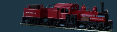
MDC 3tr Shay
Prepping the driveshaftline
January 8 & 9, 2006
Though the engine now ran satisfyingly, there was another major nerve wrecker ahead: the original Shay drive shaft, steam motor and universals. Don't, I repeat DON'T, consider working on it unless you have just had your best holiday ever and your personal coach just told you to accept new challenges. It's boring, painstaking, nerve wrecking, will make you doubt if will ever make it and finally: rewarding. That is if you do things right.
When I took my first glance in the instruction manual of this kit I wondered why there were two driveshafts: one in the center with worms and one on the right side with gears. The latter is purely cosmetical now but to my opinion it would have been easy to make it a real drive shaft. I gave it one single try and assembled the driveshaft without the gearing and worms only to see that this wasn't going to work. The inaccuracy of the gearing makes the right hand draft shaft totally unsuitable for whatever function other than purely cosmetical.

A very, very tedious job is working the universal couplings.
If deburring
them isn't enough Jeff Johnston advises, rightly so, to make a small space on
the outside of the coupling halves to allow the coupling to swivel more freely.
This will allow your model to run tighter curves, which is of course one of
the merits of a Shay. But a coupling halve sizes only a few mm's. Each halve
needs four extra spaces, I have 12 halves, which means I spent almost the rest
of the day deburring and filing minute parts. This was the must agonizing part
of the whole project. Just do it, do it well and carefully and then forget about
it as fast as you can. The Dutch say "verstand op nul, blik op oneindig",
which means as much as switch off your mind, just press on
On the left a deburred but further untreated coupling halve. Right a finished
halve.

This is the idea.
Left the universal coupling allowing the driveshaft to adapt to angular motion of the trucks. In the middle the extendable sleeve shaft which allows the shaft to adapt to differences in length when the trucks move.

This is the idea of the extendibility of the shaft. But if you extend it too
far it will simply drop out

First running trials with the drive shaft line on the rear and tender trucks

Freshly drilled holes for the screws that fix the three cylinder engine

The three cylinder engine (upside down) completely assembled with parts of the drive shaft

Trouble shooting
During running trials the tender proved to be shaking havily. Time and time again I opened the tender truck, tried to find the cause and correct it. I couldn't. Although the engine ran perfectly earlier on in the project there now seemed to be some kind of binding that caused the tender to hang in the worms every rotation or so. Finally I got fed up with it. Of the 55 hours I spend on building more than halve of it was dedicated to making the engine run. Considering that the weight of the tender is low compared to the weight of the engine and consequently will make only a small contribution to the tractive force of the locomotive I decided to remove the worm from the tender truck. So my model is driven by eight wheels and simply drags the tender along. But it runs as good as a MDC Shay will ever run with its original gearing.

Sign my
GuestBook